Assembling the Faceplate
From Spare Time Gizmos' Wiki
(Brian Lloyd)]]
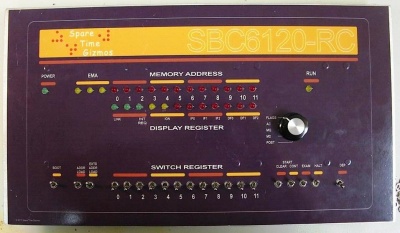
Assemble the faceplate and front side of your SBC620-RC next. The front requires that you get proper mechanical alignment of the LED indicators and the switches with the front panel. If you solder the switches in place and do not get the registration exactly right your front panel will not fit! You must test-fit the LEDs and switches before soldering them in place.
- Locate the rotary switch. With the shaft facing you rotate the shaft fully anti-clockwise until it stops.
- Remove the nut and internal-tooth lock-washer from the threaded collar on the rotary switch. Set the nut and lock-washer aside. This will expose a washer with a locking tang. Remove this washer and reposition it so that the locking tang goes through the hole with the number '5' embossed next to it. This sets the switch to have five positions. Replace the lock-washer and nut. This will hold the washer with the locking tang in place.
- Mount the rotary switch to the front of the board. Solder one pin. Make sure the switch is flush with the front of the board and the shaft is perpendicular to the board. Solder the rest of the pins.
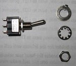
- Remove the mounting hardware from the switches. This includes the front hex nut, an internal-tooth lock-washer, and the flat washer with the index tang. This will leave the bare threaded collar of the switch with only one hex nut down near the body of the switch. Leave that nut in place.
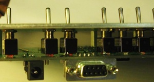
- Mount the front panel switches. You will notice that some of the toggle switches are spring-loaded to one position (momentary contact). These switches not only must go in the proper position but must be oriented properly as well. We will install the momentary contact switches first and then the two-position (on-on) toggle switches second.
- Install the switches without soldering! In the next step we will temporarily mount the front panel to hold the switches in the proper position for soldering.
□ - Mount a momentary-contact toggle switch at BOOT with the toggle facing up.
□ - Mount a momentary-contact toggle switch at LA with the toggle facing up.
□ - Mount a momentary-contact toggle switch at LXA with the toggle facing up.
□ - Mount a momentary-contact toggle switch at CLEAR with the toggle facing up.
□ - Mount a momentary-contact toggle switch at CONT with the toggle facing up.
□ - Mount a momentary-contact toggle switch at EXAM with the toggle facing up.
□ - Mount a momentary-contact toggle switch at DEP with the toggle facing down.
□ - Mount two position (on-on) toggles at SR0 through SR11 and at HALT.
- Switch all the two-position switches to the up position (with the exception of DEP). This will make it easier to maneuver the front panel over the switches.
- Remove the nut from the collar of the rotary switch. Leave the lock-washer in place. It will hold the flat washer in place.
- Take the front panel with its attached stand-offs and maneuver it over the toggle switches and the shaft of the display selector switch. When the panel is in place carefully flip the entire assembly over while holding the spacers against the circuit board. Secure the front panel to the board using eight 4-40 pan-head screws into the stand-offs. This will hold the switches in the proper position.
- Using the tip of a small screwdriver, carefully turn the hex nut remaining on the threaded collar of each switch until the nut is flush against the back side of the front panel. This will press and hold the switch in proper position against the board when you turn the board over to solder the switches.
- Turn the board and front panel assembly over. Support the front panel with a couple of small boxes along either side. That will hold the board level without pushing on the toggle switches as you solder.
- Solder the leads of all the switches.
- Remove the front panel. Remove the pan-head screws from the back of the circuit board rather than removing the flat-head screws on the front panel itself. Carefully lift the front panel away from the board.
- Install the LEDs. LEDs are polarized. You will notice that the package of each LED has a flat spot on one side. Also, the lead opposite the flat side is longer. The longer lead is the anode (+). Insert each LED into a 0.5” LED spacer. Insert each LED with spacer into the board from the front. Make sure that the longer lead goes into the upper hole (square pad marked with a +) and the lead nearest the flat spot goes into the lower hole. If you bought the kit, then notice that a green LED is supplied for the POWER position and red LEDs are used for all others.
- Be sure that the flat washer with locating tang and the lock washer are still on the rotary switch in the proper position opposite the embossed '5'.
- Once the LEDs are installed, replace the front panel. Be very careful to maneuver the front panel over the switches and the LEDs. Since the LEDs are not yet soldered into place, it is very likely that they will not line up with their holes. Using a small screwdriver from the side, adjust the leaning of each LED until it aligns with its associated hole in the front panel. When you get it right the front panel will drop down to where the spacers are flush with the circuit board. Secure the front panel to the circuit board again with the 8 pan-head screws.
- Turn the board and front panel assembly over, face-down. Again use the boxes on either side of the front panel to hold the front panel level and away from your work surface.
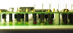
- Using your finger, press down on the leads of each LED. This will make the flat collar of each LED press up against the back of the front panel allowing all LEDs to project through the front panel by an equal amount.
- Solder the RUN LED first. Note that the leads of the RUN LED are located between U8 and U11. This is a very tight squeeze so you must be very careful not to damage either U8 or U11 while soldering. If you happened to install sockets at these locations this will be even more difficult. Be very careful.
- Solder the other 28 LEDs.
- Do a complete visual inspection. If using sockets make sure that all pins are in a socket hole. Look for any solder bridges or unsoldered pins.
When you have finished this section, proceed to Attaching the Decal.
